Transformer Fault Current Calculation Pdf
Fault current calculations using the impedance matrix Therefore the fault current at bus 2 is just the prefault voltage V f at bus 2 divided by Z 22 the driving point impedance at bus 2. Short-Circuit Current Calculations Basic Point-to-Point Calculation Procedure Step 1.

Pin On Transformers Rotating Machines
Scope This document describes the calculation of the actual accuracy limit factor F a for protection-type P current transformers CT.
Transformer fault current calculation pdf. Find the total root-mean-square fault current. 3 phase transformer fault current calculation Calculate Short Circuit Current of any Transformer in just 3 steps 1024 576 Gaurav J Gaurav J May 28 2020 June 4 2020 In this tutorial Ill explain three simple steps to calculate short circuit current of any transformer. KVAMVA rating of a transformer for.
Calculate the short-circuit current at the secondary of the transformer. Magnitude of the currents may be needed to properly size conductors conduits relays fuses circuit breakers transformers and the like. 375 KVA Overhead Transformer 10 Aluminum Multiplex Z.
All the above details will available at the transformers nameplate details. Calculation of the Current Transformer 1MRS 755481 Accuracy Limit Factor 1. System derived fault current 2.
Furthermore the calculations of currents are often needed to demonstrate that an installation will be in accordance with applicable codes as. This quick calculation can help you determine the fault current on the secondary of a transformer for the purpose of selecting the correct overcurrent protective devices that can interrupt the available fault current. From HV to LV in per unit.
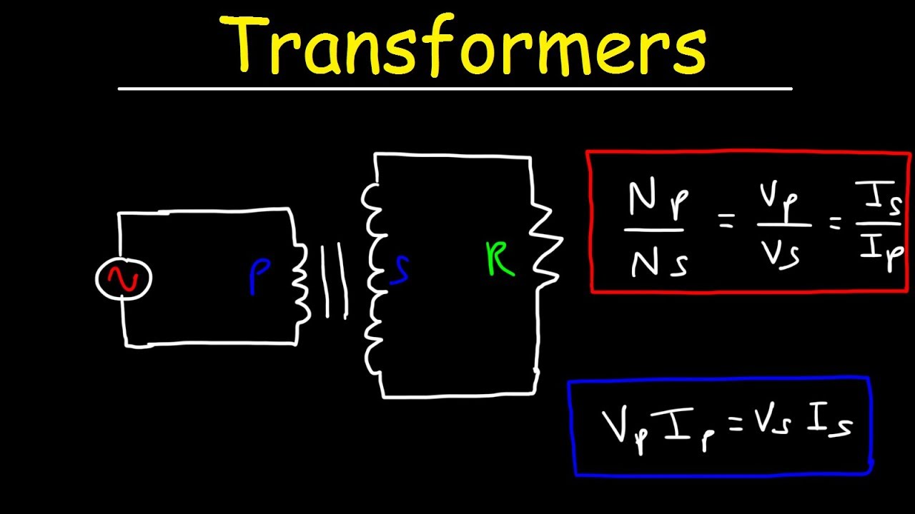
Transformer short circuit fault current Calculations. Short circuit fault current I fault in kilo amps is equal to 100 times of transformers rating S kVA in kVA divided by the multiplication of root 3 transformers secondary voltage V V in Volts and percentage impedance in percentage. Simple Methods for.
The current transformer primary is connected in series with the device in which the current is to be measured. Calculate the f factor ISC. Since Current Transformer is fundamentally a transformer it translates the current from the Pecondary side rimary to the S inversely proportional to the turns so.
Where one transformer is larger than the others in the bank use the fault current value for the larger transformer. Conversion of the mechanical inertia of rotating plant equipment connected to the system into. 12 1 12 22 2 32 3 32 22 42 4 42 22 ff ff ff ff Z V Z I V Z V V V.
Calculating Transformer Fault Current Free PDF eBooks. Using a comparative approach to analytic research the advantages and disadvantages of different reinforcement methods can be analyzed. The transformer windings resistance Rtr can be derived from the total losses as follows.
14 Three Phase Bank 3 - 375 KVA 3 Ph Sym Fault Current Amps Service Length Ft 208 240 480 0 22306 19332 9666 10 17751 16284 9267. It will also help you in deciding circuit breaker rating. The result shows that the neutral reactor.
And the last one is to find suitable reinforcement methods for the transformers which are running now. Short-Circuit Current Calculations - Cooper Industries Short-Circuit Current Calculations. The total root-mean-square fault current If is-If 3I 0 3Vp 3Rf Z 1 Z 2 Z 0 H12 Where I.
In milli-ohms where Pcu total losses in watts In nominal full-load current in amps Rtr resistance of one phase of the transformer in milli-ohms the LV and. Add motor contribution if applicable. Vsc the short-circuit impedance voltage of the transformer expressed in.
The effect of this may be to reduce the amount of current entering the ground at the far end pole ie. Embedded generators connected to the local network 3. See Note under Step 3 of Basic Point-to-Point Calculation Procedure.
Basic Point-to-Point Calculation Procedure. Major generating stations via the transmission and distribution networks ie. Procedure for Second Transformer in System Step A.
CURRENT-TRANSFORMER BURDEN All CT accuracy considerations require knowledge of the CT burden. Fault Current Full Load Amps Impedance Z Example. This permits computation of current on all sides of a transformer for a through fault eg.
Calculate the maximum fault current for a transformer rated 138kV-480Y277V 1000kVA 575Z Step 1. The flow chart in Figure 1 indicates the procedure for determining the various short-circuit currents and the resulting parameters for the different protection devices of a low-voltage. Transformer short circuit fault current.
The terms rated and base current in this paper and referenced standards however refer to the winding current which is different than the line current in the case of delta connected windings. First the calculation of the actual burden of the CT including connection wires and protection relay impedance is presented. So lets start.
Determine the transformer full load amps FLA from Multiplier 100 Z transformer 3 Faults f 1732 x L x I3 C x n x EL-L 1 Line-to-Line L-L Faults 2 xL IL-L See Note 5 Table 3 f C x n x EL-L 1 Line-to-Neutral L-N Faults. Table H1a would then contain different values of currents. The subject of these calculations.
When a fault occurs on the transmission or distribution system the current which flows into the fault will be derived from a combination of three sources. Determine the transformer full load amps FLA from. Current at the point of fault.
If satisfactory results are thereby obtained the accuracy will be satisfactory for phase-to-phase and two-phase-to-ground faults. Current must be calculated at each level in the installation in view of determining the characteristics of the equipment required to withstand or break the fault current. Transformer Fault Current Calculation Transformer Impedance Transformer Impedance is measured in Percent Impedance this is the Percentage of Rated Primary Voltage applied to the Transformers primary winding in order for the rated secondary Full Load Current to flow in the secondary winding this test is preformed with the primary winding connected to a Variac or variable supply and the.
The externalload applied to the secondary of a current transformer is called the burden The burden is. 22 f f V I Z The voltage differences at each of the nodes due to the fault current can be calculated by substitution. ReadDownload File Report Abuse.
Posted on March 20 2016. Second one is to introduce the transformer short-circuit current calculations.

Calculating Short Circuit Current Iaei Magazine
Transformers Physics Problems Voltage Current Power Calculations Electromagnetic Induction Youtube
![]()
Transformer Loading And On Load Phasor Diagrams

Pin On Power Transformers
![]()
Transformer Inrush Current Calculation Theory Electrical4u

Pin On Energy And Power

What Is Electrical Bus Bar Definition Types Of Electrical Bus Bar Circuit Globe Electricity Bus How To Be Outgoing

Pin On Pdd Project Development And Documentation

Example To Calculate Short Circuit Current For Circuit Breaker
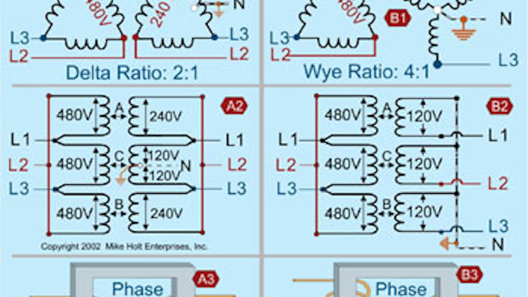
Understanding The Basics Of Wye Transformer Calculations Ec M

Calculating Short Circuit Current Iaei Magazine
![]()
Transformer Full Load Current Amps Calculation Calculator Electrical4u
![]()
Three Phase Transformer Connections And Basics
![]()
Transformer Fault Current Calculation
![]()
Base Current Calculations For An Ynd1 Transformer Download Table

Computing Short Circuit Current Of Open Delta 3 Phase Transformers Mike Holt S Forum
Transformer Short Circuit Current Calculation And Reinforcement Solutions Eep
![]()
Tertiary Winding Of Transformer Three Winding Transformer Electrical4u
![]()
Current Transformer Basics And The Current Transformer
0 Response to "Transformer Fault Current Calculation Pdf"
Posting Komentar